(ANALOG)
(DESIGN)
(MODULES)
(ASSEMBLY)
(HOME)
ARM DSP Vertical Navigation Radar
Matjaz Vidmar, S53MV
1. Design
Aviation radio altimeters are usually designed as FM radars operating in the 4.2-4.4GHz frequency band. Radio-altimeter designs differ in the number of antenna used: single antenna or two separate transmit/receive antennas, and in the type of beat-signal processing: simple beat-signal frequency counter or beat-signal spectrum analysis. A radio altimeter with two separate antennas, beat-signal spectrum analysis and a combination of synthesized-voice output, numerical and graphical display is a powerful navigation tool: a one-dimension Vertical Navigation Radar.
In this article an improved DSP version of the successful, ANALOG Vertical Navigation Radar is presented. Much of the improvement comes from DSP techniques, in particular a FFT spectrum analyzer implemented inside a low-cost ARM microcontroller. Further, the powerful ARM microcontroller considerably simplifies the hardware as shown on the block diagram of the new ARM DSP Vertical Navigation Radar:
The new ARM DSP Vertical Navigation Radar is three times faster and twice more accurate than its analog predecessor. One whole altitude measurement cycle takes 133ms in place of the former 400ms. The resolution during the critical landing flare is halved to 0.5 feet
in place of the former 1 foot. Accurate DSP filters and better averaging algorithms further improve the reliability of the instrument.
Special voice-storage chips (ISD2560) are no longer required, since the voice synthesizer is built inside the same DSP microcontroller. Since both the new altimeter and the DSP voice synthesizer are faster, blind landings are now possible even with demanding aircraft configurations, like full flaps, full air brakes and engine idle. Last but not least, the complexity and cost of the electronics is halved using powerful processors and DSP techniques.
The new ARM DSP Vertical Navigation Radar operates in the same 4.2-4.4GHz radar-altimeter frequency band. The antennas are the same and the microwave electronics is similar with just some minor improvements. The range of the new instrument is therefore the same as the old one: 0 feet to 5000 feet. The user interface a similar graphical and numerical LCD and an improved voice synthesizer.
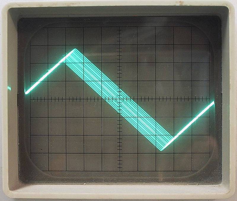
Just like in the analog design, the resolution of the new FM-radar altimeter is improved by dithering the triangular sweep waveform as shown on the following oscilloscope image:
The resulting IF beat waveform (as shown on the following oscilloscope image at a measured altitude of 0 feet) explains the effect of the dithering on the resolution:
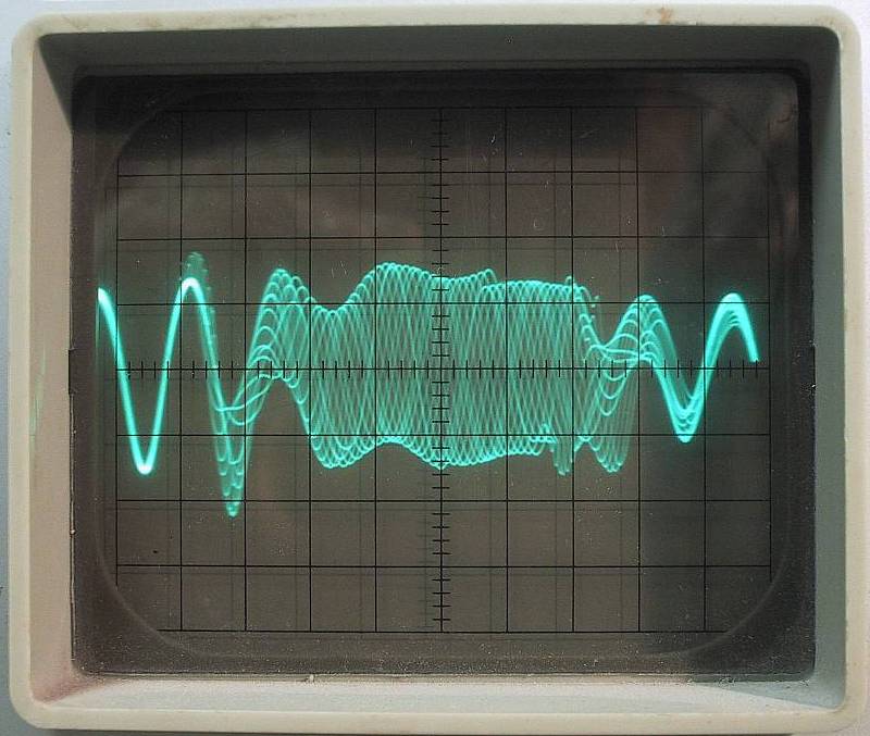
Without dithering a 150MHz sweep allows a resolution of about 3 feet (1m). Dithering improves this value to about 1 foot (30cm) using analog signal processing. Some further improvement could be obtained by a more efficient spectrum analyzer and/or a quadrature microwave-receiver front end. Accurate DSP filters can further improve the resolution down to 0.5 feet (15cm) even without a quadrature front end.
Both analog and DSP design perform a spectrum analysis of the IF beat signal. The analog design uses two IF channels and 32 different sweep rates to measure 64 spectral lines. A DSP FFT spectrum analyzer makes much better use of the measured data: it could do the same with just a single sweep rate except for the limitations imposed by the analog microwave front end.
To avoid errors caused by the Doppler shift due to the moving aircraft with respect to ground, the IF beat frequency should not be too low. On the other hand, the IF beat frequency and corresponding bandwidth should not be too high to avoid thermal noise. Regardless of the beat-signal processing, a single sweep rate is a poor solution for a wide-range altimeter operating from zero (flare) to several thousand feet.
The new ARM DSP Vertical Navigation Radar uses four different sweep rates: 1600Hz, 345Hz, 74Hz and 16Hz to divide the whole measurement range 0...5000 feet into four segments as shown on the following diagram:
The IF beat signal is sampled at 170kHz with 10-bit resolution. Each sweep rate is sampled for 18ms resulting in 3072 samples. A raised-cosine window is applied to the first 2048 samples and to the last 2048 samples. Two independent Fourier transforms are applied to each group and the power spectra of both groups are added together. A single complex 2048-point FFT is used for this purpose.
The power spectrum is weighted to compensate for the increasing signal attenuation with altitude. Finally the power spectrum is averaged into 32 groups using raised-cosine filters in a logarithmic frequency scale. Accurate power-spectrum averaging is a very efficient method to compensate for random signal dropouts caused by diffused reflection from most targets. On the other hand, power-spectrum averaging is very sensitive to pulsed interference, like ATC transponders, DMEs or other radars. Therefore efficient pulse limiting and/or pulse blanking has to be applied before the narrowband FFT filters.
One complete segment takes around 22ms depending on the signal processing. In any case some dead time is required before starting the sampling of the following sweep rate to allow the analog electronics to settle. All four segments provide in total 128 spectral lines in a logarithmic scale, resulting in a resolution of 0.5 feet during the flare and about 5% at higher altitudes.
The lowermost segment 0-42ft is measured more frequently to increase the speed, accuracy and reliability of the data during the critical flare in the same way as in the old analog design. A whole measurement cycle therefore takes 6 segments or about 133ms. All 128 spectral lines are averaged at the end of the signal processing of each segment and a full updated data set is made available every 22ms.
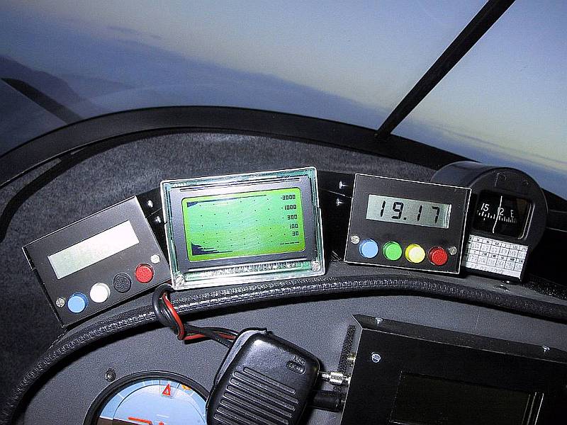
Data is transmitted to the display module through a 9600bps RS-232 interface. One whole data set includes 69 bytes of data, therefore a display-update rate of more than 10Hz is available. The display unit includes its own PIC microcontroller and a 128x64 graphical LCD module. The display format is very similar to the old analog design. Only 64 power-spectrum lines are displayed, every second (overlapping) power-spectrum line is skipped. The measured altitude is shown numerically in feet with up to 4 digits:
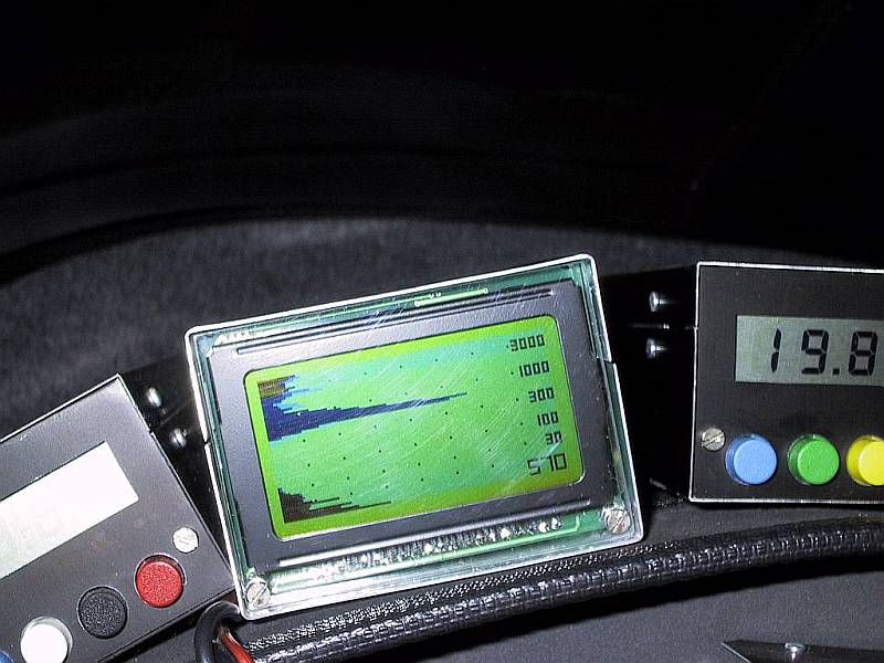
The amplitude dynamic range is 48dB, slightly less than the 55dB of the analog design. Marker dots are placed every 16 pixels or 6dB, each pixel equals 0.375dB. The valid-data threshold is placed exactly at the display center (24dB) from the experience gathered with the old analog design. A signal-level adjustment can be performed in the analog IF amplifier if required. A typical display at an altitude of 570 feet is shown on the following image:
The last spectral line #128, corresponding to an altitude of 5200feet, is used as an invalid signal marker. In this case the numerical altitude display shows four bars just like in the case of too weak reflected signal, as shown on the following image:
The voice synthesizer operates independently of the graphical/numerical display. A voice message may start as soon as the previous voice message ended and new altitude data is available after any 22ms period. No voice message is generated if the measured altitude is at least 600 feet or above and/or the measured data is found invalid.
If the measured altitude is 570 feet or below and the signal strength implies a valid measurement, one of the following voice messages is generated: zero, half, one, one-and-a-half, two, three, four, five, six, seven, eight, nine, ten, twelve, fifteen, twenty, twenty-five, thirty, forty, fifty, sixty, eighty, one-hundred, one-hundred-twenty, one-hundred-fifty, two-hundred, two-hundred-fifty, three-hundred, three-hundred-fifty, four-hundred, four-hundred-fifty or five-hundred.
Since the measurement resolution is higher than the available voice messages, the altitude is truncated to the lower available voice message. If the measured altitude requests the same voice message as already transmitted, a silence period of 6 seconds is inserted to avoid annoying the pilot. Of course a different voice message is transmitted as soon as possible, ending the silence period immediately at any time if required. Most important, the dead time between different voice messages is much smaller than in the analog design using the ISD2560 voice-storage chip.
The voice messages are recorded as WAV files at a 8kHz sampling rate and 8-bits resolution. The current files total to about 143 kbytes and are conveniently stored in the FLASH memory of the microcontroller. Since there are 500 kbytes of FLASH available in the LPC2148 and all DSP software takes less than 10 kbytes, voice messages could be stored at a higher sampling rate and/or better resolution for an even better voice quality.
The individual electronics modules of new ARM DSP Vertical Navigation Radar are described into detail in the following section. Finally, the construction, assembly and operation are described in the last section of this article.
(ANALOG) (DESIGN) (MODULES) (ASSEMBLY) (HOME)